 Figure 1
There are a lot of unclearness about the working, dimensionning, the reachable sensitivity, the range and direction accurately of 3.5 MHz direction finding antennas. But the two parameters: sensitivity and direction accurately are very important parameters of the receivers and have a big influence of the competition results in ARDF contests. The next paragraphs explain the problems, show the calculations and compare it with the praxis. Conclusions are made.
A loop antenna generates in a electrical field E (in fact we have to use the magnetic field H, but in the far field, it is allowed to use the electrical field) with a wavelength lambda a maximum voltage of:
(1) U = 2 * pi * w * A * E / lambda
When we push the ferrite in the loop (coil), the field will be grow with a multiplication factor of the relative permeability µw. This permeability is lower than the static permeability and is depend of the ferrite and coil surface.
(2) UFA = 2 * pi * µw * w * A * E / lambda
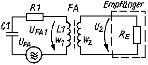
This is the reason, why the surface of the induction with ferrite is smaller as without a ferrite core for the same voltage. We become a higher signal when we put the induction in a resonance circuit tuned at the signal frequency. Matching of the resonance circuit to the low impedance receiver input will be done by a second coil.
 Figure 1
Figure 1 shows the replacement circuit of a real ferrite antenna. The voltage UFA1 is bigger as the induced voltage UFA of the electromagnetic field because we want to reckon with the quality factor of the resonance circuit.
(3) UFA1 = 2 * pi * µw * w1 * A * Q * E / lambda
 Figure 2
Transforming the replacement circuit (Figure 1) in a equivalent circuit (Figure 2) gives us the formula of the quality factor Q of the resonance circuit.
(4) Q = 1 / (2 * pi * f * L1 / Re * (w2 / w1)2 + (R1 / (2 * pi * f * L1)))
The voltage at receiver input UFA2, will be:
UFA2 = w2 * UFA1 / w1
(5) UFA2 = 2 * pi * µw * w2 * A * Q * E / lambda
The quotient U/E called also the effective height of antenna hW. The effective height of the ferrite antenna (secondary side) for a signal at the receiver input:
(6) hwFA2 = 2 * pi * µw * w2 * A * Q / lambdaFor example: A receiver FPE80 has approximate values:
The received voltage UHA at the vertical antenna of the RDF equipment:
(7) UHA = hwHA * E
We know that for a antenna (hHA ‹‹ lambda/4) just above the earth surface the effective antenna height hwa= 0.5 * hHA is.
 Figure 12
Because the vertical antenna is assembled at the receiver, and this receiver is used at a height of 1 to 2m, increased the effective antenna height (see [1]) to:
(8) hwHA = c * (hH + hHA) with c = 0.5...0.82
The factor c is dependent of the quotient hH / hHA. In a practical case for a height hH= 1...2m, we can use c=0.8 [1]. The voltage delivered by the vertical antenna becomes:
(9) UHA = 0.8 (hH + hHA) * E
When we want to calculate the input voltage of the receiver, we have to know the impedance of the vertical antenna at the place of connection with the receiver. The antenna theory tells us that a short vertical antenna (hHA ‹‹ lambda/4) in the feet point pure capacitve is. With a equivalent capacity of:
(10) Ca = hHA / 1.8 / ln (1.15 * hHA / dHA)) Ca in pF, hHA and dHA in cmExample: A vertical antenne of 26 cm and a diameter of 2 mm calculate us a feedpoint capacity of Ca= 2.9pF.
The connection of the vertical antenna with the input of the receiver can be done in different ways. Frequently, e.g. FPE80, the vertical antenna will be matched with a serie inductance and serie resistor to the input of the receiver (parallel with the ferrite antenna). The equivalent circuit is given in figure 3.
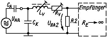 Figure 3
The equivalent resistance will be calculated form the equivalent circuit of the ferrite antenna:
(11) R2 = Q * 2 * pi * f * L1 * (w2 / w1)2
The serie inductance Lv have to be form a resonance circuit with the antenna capacity Ca and the parasitic cable capacity Ck. The vertical antenna voltage UHA2 at the input of the receiver is given by next formula:
(12) UHA2 = E * 0.8 * (hH + hHA) / (1 + Ck / Ca) / (1 + Rv / R2) with R2 like in (11)
The effective height of the short vertical antenna at input of receiver is:
(13) hwHA2 = 0.8 * (hH + hHA) / (1 + Ck / Ca) / (1 + Rv / R2)
Example:
The FPE80 receiver has:
Ck= 18pF, Rv= 1.4kOhm, w2= 3, w1= 28, hH= 1.5m,
hHA= 26cm, dHA= 2mm, Ca= 2.9pF, Q= 65, L1= 55µH
deliver R2= 925Ohm.
The equivalent vertical antenna height at the input of the receiver
amount to hwHA2= 0.078m.
The equivalent antenna height of the vertical antenna and the loop stick have to be the same for a
good front to back ratio. For the tuning of the two heights, do we have the serie resistor Rv.
In the example of the FPE80 match the theoretical calculations
hwFA2= 0.075m and hwHA2= 0.078m very good !!!
As a result of thermic noise of the loss resistance of the resonance circuit, the industrial and atmospheric noise will get the receiver noise at the input. The in figure 1 showed replacement circuit, have to be extended with the radiation resistor.
 Figure 4
In the antenna theory we find for this radiation resistor of the ferrite antenna next value:
(14) RsFA = 320 * pi4 * (w1 * µw * A)2 / lambda4
With the numbers of previews example of the FPE80, we get RsFA= 13 µOhm.
The loss resistance R1 of the resonance circuit deliver noise with temperature of 290 gradK (environment temperature), the radiation resistor deliver noise equivalent with a temperature higher as the environment temperature T0. In accordance with CCIR, Report 322 and other sources get we during the day in the 3.5MHz band a noise equivalent temperature until 3*107 gradK (without strong local interference). The relation between both sources of noise (thermic noise of the equivalent resistance) behave:
(15) Urrs / Urr1 = SQR(Tant * RsFA * Q / (T0 * 2 * pi * f * L1))
For the used example we get a relation Urrs / Urr1 ca. 0.27 (-11.4dB).
That means that the noise delivered by the ferrite antenna is bigger as delivered by the atmosphere. We calculate the noise voltage at the secondary side by:
(16) Urfa2 = w2 / w1 * SQR(k * T0 * B * Q * 2 * pi * L1)
When we look to the noise factor F of the receiver, we get for the sensitivity of the receiver (S/N=1):
(17) Egr = F * lambda * SQR(k * T0 * B * Q * 2 * pi * L1) / pi / w1 / µw / A / SQR(Q)
Example: In the case of the FPE80, we got B= 5 kHz, F= 3(10dB), so we get a sencitivity of Egr= 11µV/m.
We becoming this factor with a RDF receiver at right angles to the direction of the transmitter and
the vertical antenna not connected. That is also the sensitivity that we measure at the AF output of
the receiver circuit by means of a noise measuring. With a higher acoustic signal, we get a better result.
That's because the human ear filtered the noise better. For example, with a
AF of 1 kHz we get a equivalent BW of 50 to 100Hz. Experiments in [2] demonstrate that
a voltage of 2.3 times bigger as the noise level, it possible made to hear the
signal. The relation of the noise voltage is: SQR (5 kHz / 50...100Hz) / 2.3 = 4.3...3.1.
Depended on the characteristics of the interference and the individual competence of the ear, will the
use of the acoustic signal a factor 2 to 4 times better when we use a IF BW of 5kHz.
Interesting is the question whether the noise of the connected vertical antenna (side determining) the sensitivity inferior is to the system without the vertical antenna. The improved equivalent circuit show figure 5.
 Figure 5
The radiation resistance of the vertical antenna is:
(18) RsHA = 160 * pi2 * (hw / lambda)2 with hw=0.8*(hH+hHA)
Our example of the FPE80 becomes RsHA= 0.45Ohm. The ground and loss resistance Rv is certainly lower than 1 kOhm, so is the noise contribution unimportant in comparison with the contribution of RsHA (in opposite with the ferrite antenna).
For our example, we have a maximum noise voltage of UrHA= 1.9µV. With a field of Egr= 11µV/m is the signal UHa= 15.5µV. The noise delivered by the vertical antenna is much more lower than the delivered signal. The sensitivity with a connected vertical antenna will be improved to 5.5 µV/m because the noise ratio of the vertical antenna is much more better than the noise ratio of the ferrite antenna. There is a good accordance between the calculated values and what we have measured.
The received field is depended of the radiated power (this is depended of the transmitter power, the antenna matching, antenna length and the ground conditions at the transmitter side), the conducting of the ground, the land (hills,...), and most important, the distance between receiver and transmitter. For a distance of more than 200 m, there is a quadratic decreasing of the field strength. A transmitter with a input of 3 W and a antenna length of 6 m delivered a accessibility of 0.05 W in the air. With a average ground conductance induce this field a voltage of 0.5 mV/m in a circle of 1 km. A field of 11 µV/m be situated in a environment of
(20) R = SQR(0.5 mV/m / 11 µV/m) * 1 km = 6.7 kmWe become in our example, without vertical antenna, we become a distance of 6.7 km for a S/N= 1.
Figure 6 shows the dimension of the signal in the different parts of the replacement circuit for received electrical field of E= 100µV/m.
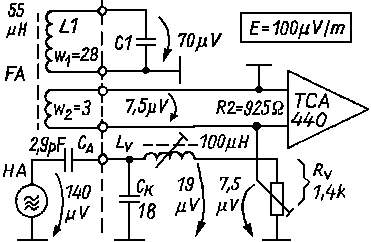 Figure 6
Until now, all given calculations are done for the ferrite antenna. For the loop the calculation is done in the same way, only µw= 1. Interesting is to know how big the loop have to be, to get the same signal as the ferrite antenna. We presume for this calculations the same quality factor as for the ferrite antenna and a magnetic connection to the receiver. With formula (5), we calculate a diameter of 14 cm for the same voltage of ferrite antenna and loop antenna. Most of the time, the loops are much more bigger (>20 cm), that means, the sensitivity improves a lot. With a diameter of 20 cm will the signal two times so big. That means a enlargement of the receiver range of 1.4 times. With a diameter of 28 cm is the voltage 4 times as bigger (two times the original range).
With a loop antenna, is the fox hunter receiver not so easy to carry, but the sensitivity is most of the time much bigger. It is also possible to improve the sensitivity of the ferrite receiver with a very big, magnetic coupled loop antenna. It would be possible to build this antenna in the clouds of the fox hunter. In the case of a good position of the hunter, the definitely higher voltage of the loop (e.g. 1m diameter), will be coupled with the ferrite of the receiver. Due to this construction, the sensitivity of the receiver will be increased.
In the previous chapters, we didn't consider the position the ferrite core in comparison with the transmitter, or better in comparison with the received magnetic field. We obtain the very known eight characteristic when the angle between the transmitter direction and the axis of the ferrite rod is changed, or the cardiogram when the vertical antenna is connected (look figure 7/13/14/15).
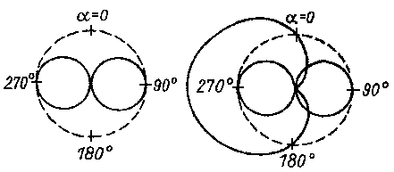 Figure 7
While the evaluation is made by the human ear, and the ear only a distinction of 1dB= 10% distinguish, will the direction finding done by the minimum of the eight circle, like in figure 10 shown.
 Figure 10
This is because a minimum delivering a much better change in the volume by
a change in angle. It is impossible determining the side in which the transmitter
is located only with the minimum measuring. The use of the minimum results
also in other problems: a continue change in field since the height of the receiver
in relation to the ground changed, the ground conduction changed, the distance
to the transmitter changed. All this factors makes it difficult to do a accurate
direction finding.
The possible exactness of the direction finding is depended on:
 Figure 8
For a certain S/N ratio get we an angle alpha :
(21)  sin alpha = Unoise / Umax * S/N  ->  Egr / E * S/N
          alpha = arcsin (Egr / E * S/N)
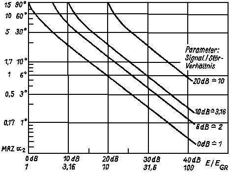 Figure 11
Figure 11 shows that with a reduced signal (increased range), the sharpness increased, and with a better receiver sensitivity, the sharpness improved. By partition of the measured angel, the accuracy can improved by a factor 1 to 3.
In spite of a bigger signal in the case of a loop antenna, is it sufficient to use a normal ferrite rod receiver (with a core of 8 to 10 mm diameter and a length of 120 to 200 mm). Formula (17) shows why this so is and how we can improve the 3.5MHz receiver. In formula (17) are the parameters f, pi, k, T0, lambda constant or to be considered independent. It is also for the relation: SQR(L1)/w1, because the induction is squared dependent of the number of turns. Also a bigger coil surface doesn't work because the average of the permeability in the same way decreases as the surface grows. It is possible to improve next factors:
When this optimize factors are used up, it is still possible to increase the coil surface and the same time the effective ferrite surface. Or we use more than one ferrite for the same coil, or every rod hat his own coil (see [3]). It is also possible to change the coil wind, with a coil elongated on the whole length of the rod (1 to 3dB), see [4]. By this way, a better receiver can be build, but the receiver will be heavier.
More conclusions can be made by formula (12).
 Fig.13
 Fig.14
 Fig.15
The height in which the receiver will be used, will be a determinative factor.
Because the used height is 5 to 10 times bigger as the vertical antenna, this height
will determined the delivered signal strength. This is also the reason why the side
determination just above the ground doesn't work. The received voltage is only
10 to 20% of the normal signal (figure 15). This is the reason why the matching
coil and serie resistance have to be tuned when the receiver be situated at the
height of use. For an optimal tuning of the forward/back ratio the tuning will
be done in a height of 1.5m (figure 13).
The figures 13/14/15 shows the influence of the height (1.4m / 2m / 0.2m) on the signals.
In the equation (12), we find also the relation Ck / Ca. This has to be as low as possible. As we can seen in figure 6, form this two capacities, CA the vertical antenna capacity and Ck the parasitic capacity, a signal divider. When we want to get a big input signal, the input capacity Ck has to be as low as possible.
 Figure 16
It will be done by short connection wires, a serie inductance or with the use
of a low capacity HF amplifier (e.g. a FET with low input capacity Cinput <10pF
in the direct environment of the vertical antenna, see [1]. In this way, it will be
possible to use a 5 cm long vertical antenna).
Figure 16 shows the principle of a antenna amplifier with a bipolar transistor and
magnetical coupled with the input of the receiver throught the ferrit rod.
| FPE80 | ARDF receiver 'Greif', was produced in Greifswald/Germany |
| FA | Ferrite antenna |
| HA | Vertical antenna (antenna for finding side of direction) |
| A | Surface of ferrite coil or loop antenna |
| B | (Noise)Bandwith of the complete receiver |
| c | Constante for calculation of effective height HA (here c=0.8) |
| Ca | Capacity at HA feedpoint |
| Ck | Parasitic capacity at HA feedpoint |
| C1 | Total capacity of FA resonance circuit primary and transformed secundary |
| dHA | Diameter of HA-rod |
| E | Electrical field at antenna |
| Egr | Noise depended sencitivity |
| f | Working frequency approximately 3.6 MHz |
| F | Noise factor of receiver |
| hH | Height of receiver (from feedpoint HA of antenna until the earth) |
| hHA | Lenght of HA |
| hwFA2 | Effective FA height, calculated to receiver input |
| hwHA | Effective HA height, calculated to feedpoint HA |
| hwHA2 | Effective HA height, calculated to receiver input |
| K | Constant of Boltzmann = 1.38E-23 Ws/K |
| lambda | Wavelenght approximately 83 m |
| Lv | Inductivity of serie coil (for the compensation of Ca and Ck) |
| L1 | Inductivity of FA-coil |
| pi | 3.14159... |
| Q | Quality factor of FA resonance circuit |
| R | Receiving range of ARDF reciever for a S/N=1 |
| Re | Inputresistance |
| R1 | Lossresistance of FA-resonance circuit (primair) |
| R2 | To secudair side calculated resistance |
| RsFA | Wellenresistance of FA (noise depended of Tant) |
| RsHA | Wellenresistance of HA (noise depended of Tant) |
| S/N | Signal/noise ratio |
| T0 | Environment temperature, Noisetemperature of loss resistance (290 gradK) |
| Tant | Antenna noise temperature (‹ 3E7 gradK) |
| UFA | in the FA induced inputvoltage |
| UFA2 | FA-receiver voltage of receiver input |
| UHA | HA-receiver voltage of receiver input at feedpoint |
| UHA2 | at receiver input delivered received voltage of HA |
| UrFA2 | at receiver input delivered received noise voltage of FA |
| UrHA | HA-noise voltage at feedpoint of HA |
| w1 | Turns of primary FA coil |
| w2 | Turns of secundary FA coil |
| SQR | Square root |
[1] Lindemeier, H.: Die transistorisierte Empfangsantenne mit kapazitiv hochohmigem Verstärker als optimale Lösung für den Empfang niedriger Frequenzen. Nachrichtentechnische Zeitschrift 27 (1974), H.11, S.411
[2] Eine verbesserte Antenne für den Rundfunkempfang. Funkschau 52 (1980), H.9, S.74
[3] Rajchl, M.: Verbesserter Empfang für Fuchsjagd-Empfänger. Amaterske Radio (CSSR), 22 (1973), H.4, S.155
[4] Meissner, S.: Der Hochleistungs-Funkpeilempfänger FPE80L.
Funkamateur 1983 H.8 S.396
times read since 25.3.99